Engine body
What is the engine body ?
The engine body is the main part of the engine, and is broadly classified into the cylinder system, the main motion section, and the valve train mechanism.
The cylinder system comprises the cylinder block (crankcase), cylinder head, etc., the main motion section comprises the piston, connecting rod, crankshaft, etc., and the valve train mechanism comprises the valves, etc.
(1) Cylinder system
1) Cylinder block
The cylinder block forms the frame of the engine, holding the cylinder inside, and together
with supporting the crankshaft, cam axis, etc., the cylinder head is attached via the head gasket. Also, passages for coolant and lubricant have been provided by way of the cooling system and lubricating system.
The materials that are generally used for the cylinder block are aluminum alloy in the case of gasoline engines, and cast iron for diesel engines.
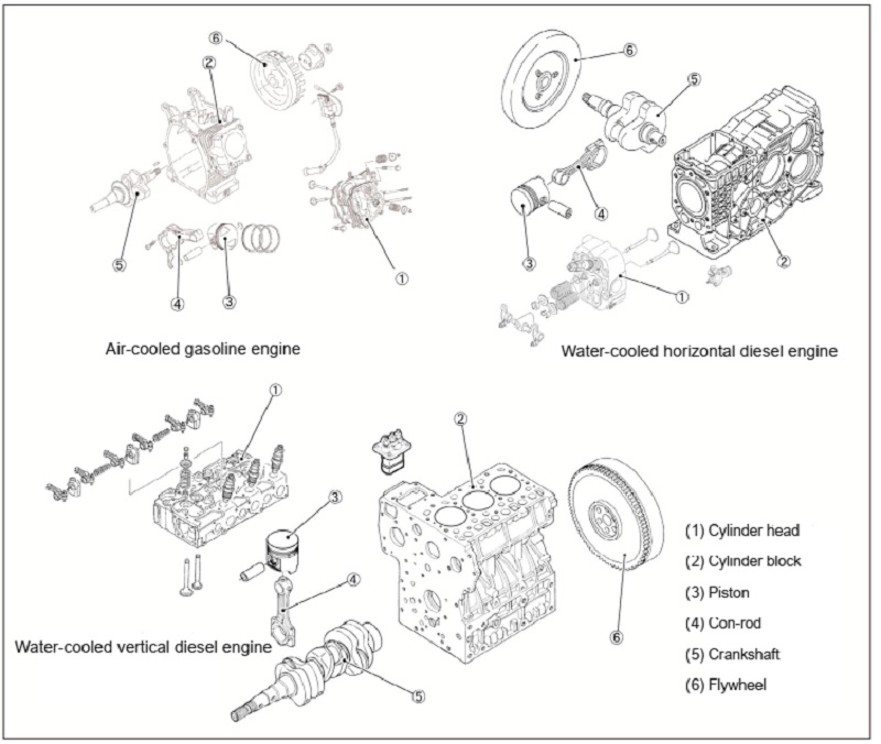
(1) Cylinder head
(2) Cylinder block
(3) Piston
(4) Con-rod
(5) Crankshaft
(6) Flywheel
2) Cylinder head
The cylinder head is mounted on the cylinder block, forming the cylinder, piston, and combustion chamber (the space where the actual combustion occurs).
The structure of the cylinder head differs depending on the engine type, cooling system, combustion system, valve mechanism, and so on.
(2) Main motion section
1) Piston
The piston forms the cylinder, cylinder head, along with the combustion chamber, and moves in a reciprocating motion inside the cylinder for each of the suction, compress, explosion, and exhaust strokes. The most significant role of the piston is to receive the explosive power, and transmit that power to the crankshaft through a connecting rod.
A piston is generally made from aluminum alloy, with the top of the piston referred to as the
piston head, and the lower part is called the skirt. The side close to the piston head normally has 3 to 4 square-shaped grooves, with piston rings inserted.
A diesel engine has a high compression ratio, with a small clearance between the piston and cylinder, with some engines having a recessing (valve recess) so that the piston does not hit the valve when activated. Also, the swirl chamber type has recessing to efficiently diffuse the combustion gas that is ejected from the swirl chamber. On the other hand, the direct injection type has a cavity in the piston head that becomes the combustion chamber.
2) Piston ring
Piston rings are inserted into the piston ring grooves, and broadly perform 3 roles. The first role is to maintain the airtightness of the combustion chamber for compression and combustion gas pressure, so that there is no leakage to the crankcase. The second role is to transmitthe heat received by the piston to the cylinder wall. The third role is to scrape off oil that has adhered to the cylinder wall, so as to leave the absolute minimum oil film, while at the same time, preventing excess oil from entering the combustion chamber.
The piston rings comprise compression rings, which are mounted on the top of the ring grooves, and the oil rings, which are mounted underneath.
- Compression rings
The compression rings are referred to as (from the top) the top ring, the second ring, and the third ring. The ring shapes are as follows, and the mounting locations are selected according to conditions such as the engine type.
Plain shape:
The ring is in contact with the cylinder wall, preventing compression leakage andgas leakage. Also, some have a barrel-faced (arc shape) contact surface with the cylinder wall that have a good initial fit, preventing abnormal wear and scorching. This is used as the top ring.
Keystone shape:
Has resistance to heavy loads, and is greatly effective in preventing ring stick (adherence to the ring groove of the piston). Similarly to the plain-shaped ring, there are some that have a barrel face (arc shape). There are some rings that are tapered on one side only (top surface), keystone-shaped on one side, tapered on both sides, and keystone-shaped on both sides. This is used as the top ring.
Inner cut shape:
Functions the same way as the keystone-shaped ring, and is contact with the line in the ring groove, preventing oil from passing the rear side of the ring and rising. Moreover, when explosive pressure is added, twisting is corrected so that the full surface is in contact with the cylinder wall. This is used as the top ring and second ring.
Taper face shape:
The outer circumference is tapered, and the line is in contact with the cylinder wall, so the initial fit is good, so that it slides on the oil while the piston is rising, and scrapes the oil while the piston is lowering. Therefore, it maintains airtightness, and prevents the oil from rising. This is used as the second ring.
Under-cut shape:
This is even more effective than the taper face-shaped ring in preventing oil from rising. This is used as the second ring and third ring.
- Oil ring
A groove is generally cut into the outer circumference of the ring, with oil return holes at equal intervals inside the groove. There is also a hole in the oil ring groove of the piston, and the scraped oil is returned to the crankcase via this hole.
Bevel cutter shape:
The top and bottom edges of the cylinder wall contact surface are beveled (angled cut), obtaining high surface pressure, which provides high performance oil scraping. There are some rings that have an expander added to the inner surface of the ring to provide increased tensile strength, greater flexibility, and enhanced performance for scraping off the oil.
Combination ring:
Two thin sheet-shaped rings are placed on the top and bottom, and a waveshaped plate is inserted in-between, and are placed inside one groove as a whole. The wave-shaped plate functions as a spring, pushing the outer circumference of the ring against the cylinder wall.
3) Connecting rod
The connecting rod connects the piston and crankshaft, and performs the function of transmitting the explosive pressure received by the piston to the crankshaft.
The part that connects to the piston is referred to as the small end, and the part that connects to the crankshaft is the big end. The big end is a split-type, with the connecting rod cap tightened with a special bolt designed to provide accurate orientation and positioning.
The connecting rod is subject to large force, so is made of special steel, with many rods being a "|" shape, which is lightweight yet has sufficient strength. Also, an oil passage runs from the big end of the connecting rod to the small end to facilitate lubrication of the piston pin and cooling of the piston.
The connecting rod of a gasoline engine is made of light alloy, with the rod base material of both the big end and small end also serves as a bearing. An oil spoon is attached to the connecting rod cap for the lubrication method that involves splashing of oil on to the piston and bearing sections.
4) Crankshaft
The role of the crankshaft is to convert the reciprocating motion of the piston that receives the explosive pressure into rotary motion, and lead this motion to the engine exterior as continuous power.
The crankshaft comprises the following sections:
Crank journal: Becomes the rotational center at the section of the crankshaft supported by the cylinder block.
Crankpin:
The axis section for connecting the big end of the connecting rod.
Crank arm:
The section that connects the crankshaft and crankpin.
Balance weight:
A weight used to take the balance of the rotation or weight, in order to minimize vibration. On vertical water-cooled diesel engines, because the crankshaft receives the axial force, and in order to adjust the play (side clearance), side metal has been built into the journal on the flywheel side.
5) Flywheel
The flywheel is mounted on the crankshaft of the engine. The momentum of the flywheel enables the crankshaft to be rotated smoothly
(3) Valve mechanism
1) Driving the valve
A four-cycle engine has valves for taking the air (oxygen) required for combustion of fuel into the combustion chamber. The valve used for sucking in air or air-fuel mixture is referred to as the inlet valve (intake valve), and the valve for discharging combustion gas is the exhaust valve.
Generally, the same "mushroom shape" valve is used for both the intake and exhaust valves, with one or more of each fitted on each cylinder. The series of mechanisms in place to open and close these valves at the appropriate timing so that the pistons move continuously, is called the valve mechanism.
The valve mechanism is divided into the side valve-type and overhead valve type, depending on the mounting position of the valves.
Side valve type:
The valves are not on the cylinder head but instead arranged on the side of the cylinder, therefore the structure is simple, and this type allows a lower overall
height of the engine.
Overhead valve type:
Because the valves are at the top of the piston, the intake and exhaust efficiency is good. Moreover, depending on the position of the camshaft, there are broadly 3 types of overhead valve: OHV, OHC, and DOHC. Most current engines use this type.
2) Valve timing
In order to improve engine performance, it is necessary to improve the intake efficiency of air or air-fuel mixture and efficiently discharge combustion gas. By taking in a large amount of air, a large amount of fuel can be burned, allowing generation of a lot of thermal energy.
The intake valve and exhaust valve are designed to open and close at the timing described
below, in order to take in and discharge efficiently.
■ Intake valve
If the valve began to open as the piston starts to lower, negative pressure would be created
inside the cylinder, preventing efficient intake, so the valve begins to open before the piston
reaches top dead center. Even if the piston reached bottom dead center, negative pressure would occur inside the cylinder, or the inertia trying to enter the cylinder would work in the intake manifold, so because intake efficiency is better when the valve is open, the valve closes after reaching the bottom dead center.
■ Exhaust valve
As for the open timing of the exhaust valve, the valve begins to open before the piston reaches the bottom dead center, so that the combustion gas (exhaust gas) can be discharged using its own pressure. As for the close timing of the exhaust valve, the inertia works in the same way as the intake stroke, so for good exhaust efficiency, the valve closes after the piston reaches the top dead center.
Both the intake valve and exhaust valve are open together in the vicinity of the top dead center when the exhaust stroke ends and the suction stroke begins. This is referred to as valve overlap, and the top dead center at this time is called the overlap top dead center.
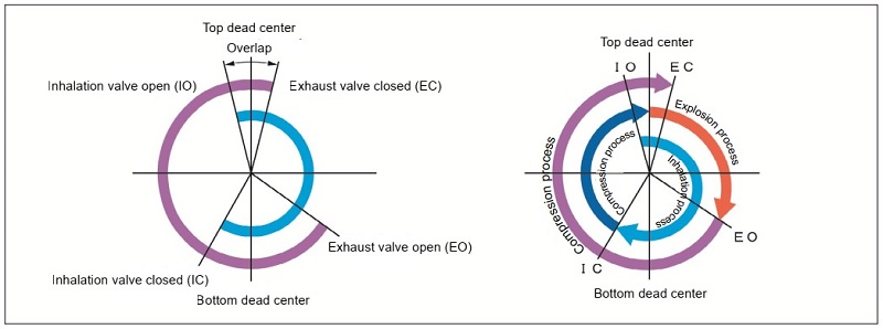
IO: Inlet open
IC: Inlet close
EO: Exhaust open
EC: Exhausent close


